


Next: Tait-Bryan Angles Up: Fundamentals of Computer Vision Previous: Implicit 3D Modeling: RBFs
|
Rotations are isometric transformations of Euclidean space, that is, transformations that preserve the length of vectors and leave a locus of points unchanged in space, equal to a hyperplane (the center of rotation in the two-dimensional case or an axis of rotation in the three-dimensional case).
The set of all Rotation Matrices  in
in  è defined as Special Orthogonal
 |
(A.1) |
 .
For
.
For  , the group of three-dimensional rotations
  is obtained, which will be the main object of interest in what follows.
There are two possible conventions for defining a rotation matrix: some authors prefer to write the matrix that transforms sensor coordinates into world coordinates, while others use the opposite convention. The rotation matrix itself has the dual role of indicating a rotation within a reference frame (Active or Alibi), or a coordinate transformation from one reference frame to a second reference frame (Passive or Alias).
In this book, matrices are predominantly used to represent changes of basis and, whenever possible, the source and destination reference frames are clearly indicated.
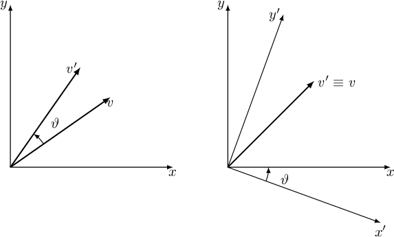
To discuss rotation matrices and make some interesting observations, it is useful to begin by analyzing the two-dimensional case, shown schematically in figure A.1.
It can be verified that  has only one degree of freedom.
The matrix
has only one degree of freedom.
The matrix
 , which represents a two-dimensional rotation, can be written in the form
As can be seen in figure A.1, when discussing a rotation through an angle  , the same transformation can be viewed in different ways, depending on the reference frame in which the observer is fixed.
The matrix
, the same transformation can be viewed in different ways, depending on the reference frame in which the observer is fixed.
The matrix
 makes it possible to rotate a vector counterclockwise (with respect to the origin of the reference frame) by an angle (left-hand figure in A.1)
A.1.
The matrix of the form (A.2), in addition to rotating a vector counterclockwise, also makes it possible to obtain the so-called “world” coordinates of a point when the “sensor” coordinates are known and it is known that the sensor is rotated by an angle (right-hand rule) in the “world” reference frame.
The matrix (A.2) therefore makes it possible to convert from “sensor” coordinates to “world” coordinates, while the inverse of this matrix makes it possible to convert from “world” coordinates to “sensor” coordinates.
makes it possible to rotate a vector counterclockwise (with respect to the origin of the reference frame) by an angle (left-hand figure in A.1)
A.1.
The matrix of the form (A.2), in addition to rotating a vector counterclockwise, also makes it possible to obtain the so-called “world” coordinates of a point when the “sensor” coordinates are known and it is known that the sensor is rotated by an angle (right-hand rule) in the “world” reference frame.
The matrix (A.2) therefore makes it possible to convert from “sensor” coordinates to “world” coordinates, while the inverse of this matrix makes it possible to convert from “world” coordinates to “sensor” coordinates.
The distinction between Inner/Active/Alibi Transformation and Outer/Passive/Alias Transformation is another way of describing the difference between rotations. These terms are often used in mathematical and physical contexts to clarify whether a transformation acts on the reference frame itself (the reference frame is rotated or translated, while the objects remain fixed in space, hence alias or passive) or on the objects within a fixed reference frame (the objects are rotated or translated, while the reference frame remains unchanged, hence alibi or active).
The rotation matrix is also called the Direction Cosine Matrix (Direction Cosine Matrix, DCM), since the columns of the transformation matrix correspond to the coefficient matrices of the old basis vectors expressed with respect to the new basis.
In this book, since we are effectively working with sensors (and not robotic arms), all matrices are in fact change-of-basis matrices, since the main objective is to determine the coordinates of a point viewed by a sensor in the higher-level reference frame, or vice versa.
Moving to the three-dimensional case, the discussion becomes even more complicated: there are infinitely many parameterizations for expressing a rotation from three independent parameters. Only in the last section A.4 of this chapter will it be shown how these parameters can be interpreted as elements of the Lie algebra
 associated with the rotation group .
It is, for example, possible to define a rotation as the composition of three elementary rotations about one of the three axes, but since matrix multiplication is not commutative, there are nevertheless 24 ways to compose these three matrices.
Combinations of matrices are denoted as Euler sequences followed by three numbers indicating the order in which the rotations are combined: 1 for the  axis, 2 for the
  axis, and 3 for the
  axis.
In robotics, the representation using Euler angles (ZYZ sequence) or that using Tait-Bryan angles (Euler sequence 321 or ZYX) is widely used; see the following section A.1 for detailsA.2.
In the Italian literature, the six groups (XYZ, YZX, ZXY, XZY, ZYX, YXZ) are called Cardano angles.
axis.
In robotics, the representation using Euler angles (ZYZ sequence) or that using Tait-Bryan angles (Euler sequence 321 or ZYX) is widely used; see the following section A.1 for detailsA.2.
In the Italian literature, the six groups (XYZ, YZX, ZXY, XZY, ZYX, YXZ) are called Cardano angles.
This angle system nevertheless has some singularities that limit its use. Alternatively, the notation proposed by Rodrigues (section A.2) or quaternions (section A.3) can be used to overcome this problem.
Again because matrix multiplication is not commutative, in three-dimensional space there is an additional level of ambiguity due to the order in which rotations with Euler angles are described, since rotations can be defined as extrinsic or intrinsic:
Regardless of the geometric meaning assigned to the rotation matrix, several observations can nevertheless be made.
As already stated above, the definition of the matrix  in the pin-hole camera equation was established, both for convenience and by convention, so as not to rotate a vector (which would instead be a conversion from “sensor” coordinates to “world” coordinates), but rather to remove the rotation of world points when the camera orientation itself is known; that is, it makes it possible to convert from “world” coordinates to “camera” coordinates.
Deriving an expression for the matrix in the form expressed in the pin-hole camera model means finding a matrix that transforms a point from “world” coordinates to “camera” coordinates; therefore, the inverse matrix of the rotation matrices that can be found in the following sections must always be used.
Let there therefore be a generic rotation
 that transforms from local, moving, “sensor” coordinates (body coordinates in the general case) to global, fixed, “world” coordinates: the matrix
 will therefore be the matrix that converts from world coordinates to sensor coordinates.
However, since the camera/image reference frame is a Left-Bottom-Front system (X increasing to the right, Y increasing downward, Z representing depth, as in figure 9.3), which differs from the Front-Left-Up sensor/world reference frame (Z increasing upward, X representing depth, and Y increasing to the left, as in figure 9.4) typical of the automotive environment, it is necessary to define a matrix
When working in an aeronautical or naval context, it may instead be necessary to move from the camera/image system to a Front-Right-Down system (for example, NED). In this situation, the permutation matrix is
Under these considerations, the matrix that converts from “world” to “camera”, the formalism normally used in the pin-hole camera equation, has the expression
 , may be referred to in the literature as a “rotation matrix” and also denoted by the letter .



