


Next: Properties of the Rotation Up: Pin-Hole Camera Previous: Lens Distortion
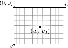
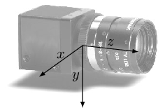
|
When dealing with practical problems, it is necessary to move from a reference frame attached to the camera, where point
 coincides with the focus (pin-hole), to a more general reference frame that better suits the user's requirements, where the camera is located at a generic point in the “world” and oriented arbitrarily with respect to it.
This applies to any generic sensor, including non-video sensors, by defining relationships that make it possible to transform points from world coordinates to sensor coordinates and vice versa.
coincides with the focus (pin-hole), to a more general reference frame that better suits the user's requirements, where the camera is located at a generic point in the “world” and oriented arbitrarily with respect to it.
This applies to any generic sensor, including non-video sensors, by defining relationships that make it possible to transform points from world coordinates to sensor coordinates and vice versa.
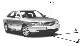
At this point, a clarification is necessary concerning the terminology related to reference frames used in this book: the “world” reference frame is defined as the frame that, in each context, is considered absolute and fixed, with respect to which the sensor is positioned. For example, in Figure 9.4, the origin of the “world” frame is associated with a point on the vehicle (the front point, for example). In this case, the “vehicle” (body) and “world” (world) frames are synonymous. This distinction disappears, however, when a vehicle moves with respect to a “world” that can once again be defined as the fixed reference frame. In that case, we have sensor coordinates, the local vehicle/body coordinates, and finally world coordinates. Usually, however, the axis convention distinguishing the sensor, vehicle, and world frames is kept consistent.
If the special role of coordinate  in camera coordinates is due to purely mathematical reasons, namely the use of homogeneous coordinates, which during projection requires the first two components to be divided by the third, this restriction does not apply to “sensor” coordinates.
Although not imposed in any way, this book uses the system shown in Figure 9.4 (ISO 8855) as the “sensor”, “body”, and “world” frame, assigning the height of the point above the ground to axis .
in camera coordinates is due to purely mathematical reasons, namely the use of homogeneous coordinates, which during projection requires the first two components to be divided by the third, this restriction does not apply to “sensor” coordinates.
Although not imposed in any way, this book uses the system shown in Figure 9.4 (ISO 8855) as the “sensor”, “body”, and “world” frame, assigning the height of the point above the ground to axis .
Therefore, to derive the final equation of the pin-hole camera, we start from Equation (9.10) and apply the following considerations:
 (which is nevertheless a rotation) to obtain the final reference frame;
 and therefore does not coincide with the axes of the “world” reference frame;
but lies at a generic point
and therefore does not coincide with the axes of the “world” reference frame;
but lies at a generic point
 expressed in world coordinates.
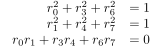
The conversion from “world” coordinates to “camera” coordinates, being a composition of rotations, is itself a rotation described by equation
 .
.
Let
 be a point in “world” coordinates and
 the same point in “camera” coordinates.
The relationship between these two points can be written as
the same point in “camera” coordinates.
The relationship between these two points can be written as
 is a
is a  matrix that converts world coordinates to camera coordinates and accounts for the rotations and the change in the sign of the axes between world and camera coordinates (see Appendix A), while the vector
 with respect to the origin of the world frame, expressed in the camera coordinate system.
Recall that rotation matrices are orthonormal matrices: they have determinant 1 and therefore preserve distances and areas, and the inverse of a rotation matrix is its transpose.
Matrix and vector
 can be combined into a
  matrix by exploiting homogeneous coordinates.
This representation makes it possible to write, in an extremely compact form, the projection of a point expressed in homogeneous world coordinates,
, onto an image point with homogeneous coordinates
matrix by exploiting homogeneous coordinates.
This representation makes it possible to write, in an extremely compact form, the projection of a point expressed in homogeneous world coordinates,
, onto an image point with homogeneous coordinates
 :
:
This equation makes it clear that each image point  is associated with infinitely many world points
lying on a line as parameter
is associated with infinitely many world points
lying on a line as parameter  varies.
Suppressing and collecting the matrices yields the final equation of the pin-hole camera (which does not and must not account for distortion):
![$\mathbf{P} = \mathbf{K} [ \mathbf{R} \vert \mathbf{\tilde{t}}_0 ]$](img1623.svg) has been defined as the projective matrix (camera matrix), which will be used later (Str87).
Matrix
has been defined as the projective matrix (camera matrix), which will be used later (Str87).
Matrix  is a matrix and, being rectangular, is not invertible.
It should be noted that by imposing an additional constraint on the points, for example  , matrix reduces to an invertible matrix, which is exactly the homography matrix (see Section 9.3.1) of the perspective transformation of ground points.
Matrix
, matrix reduces to an invertible matrix, which is exactly the homography matrix (see Section 9.3.1) of the perspective transformation of ground points.
Matrix
 is an example of an IPM (Inverse Perspective Mapping) transformation for obtaining a top-down view (Bird eye view) of the scene being imaged (MBLB91).
The inverse relationship corresponding to Equation (9.24), which transforms image points into world coordinates, can be written as:
varies) passing through the pin-hole () and oriented in the direction
 is the function that associates each image point with the vector joining the pin-hole to the corresponding sensor point.
Using the Camera Matrix
![$\mathbf{P} = \left[ \mathbf{P}_{3 \times 3} \vert \mathbf{p}_4 \right]$](img1629.svg) directly, it is possible to obtain a result equivalent to Equation (9.26) in the form
directly, it is possible to obtain a result equivalent to Equation (9.26) in the form


![\begin{displaymath}
\lambda \begin{bmatrix}
u_{i} \\
v_{i} \\
1
\end{bmatri...
...] \begin{bmatrix}
x_{i} \\
y_{i} \\
z_{i} \\
1
\end{bmatrix}\end{displaymath}](img1620.svg)



