


Next: Three-Dimensional Reconstruction Up: Multi-Camera Vision Previous: Relationship with the Relative
The preceding chapters repeatedly noted that a single image cannot provide the world coordinates of the points comprising the image without additional information.
|
Given the pin-hole camera equation (9.26), the only information that a generic image point  can provide is a relationship among the (infinite) world coordinates
  subtended by the image point, that is, the locus of world coordinates whose projection would produce exactly that particular image point.
This relationship is the equation of a line passing through the pin-hole
subtended by the image point, that is, the locus of world coordinates whose projection would produce exactly that particular image point.
This relationship is the equation of a line passing through the pin-hole  and the sensor point corresponding to image point .
Writing equation (9.26) again, it is easy to see the relationship between the parameters of camera i, the image point
and the sensor point corresponding to image point .
Writing equation (9.26) again, it is easy to see the relationship between the parameters of camera i, the image point  , and the line representing all possible world points subtended by :
 has the same meaning as in equation (9.27), namely, the direction vector from the pin-hole to the sensor point.
As follows from the preceding relationship, a single image measurement determines only the optical ray associated with the observed pixel. The three-dimensional point is therefore known only up to the depth parameter
has the same meaning as in equation (9.27), namely, the direction vector from the pin-hole to the sensor point.
As follows from the preceding relationship, a single image measurement determines only the optical ray associated with the observed pixel. The three-dimensional point is therefore known only up to the depth parameter  along that ray.
In stereo vision, we have two sensors and must therefore define two reference frames with respective parameters
 and
and
 and pin-hole positions
  and
and  , all expressed in world coordinates.
The line (10.9), consisting of the world points associated with image point  seen in the first reference frame, can be projected into the view of the second camera:
, while vector  is always constant and does not depend on the point under consideration.
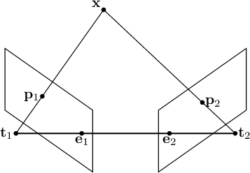
This constant point is the epipole. The epipole is the intersection point of all epipolar lines and represents the projection of one camera's pin-hole into the other camera's image, that is, the “vanishing point” of the epipolar lines.
For two cameras, the projections of the pin-hole coordinates  and
and  onto the opposite image are
 and
and  are the projection matrices.
Points
are the projection matrices.
Points  and are the epipoles.
If the definitions of the relative poses expressed in (10.4) are substituted into equation (10.11), the image coordinates of the epipoles, understood as the projection of one camera's pin-hole into the other image, are
and are the epipoles.
If the definitions of the relative poses expressed in (10.4) are substituted into equation (10.11), the image coordinates of the epipoles, understood as the projection of one camera's pin-hole into the other image, are
 |
(10.12) |
By construction, matrix  converts camera 1 coordinates into camera 2 coordinates, and represents the position of camera 1's pin-hole expressed in the reference frame of camera 2.
The lines generated by points in the first image all pass through the same point formed by projecting pin-hole onto the second image:
in fact, the world-coordinate point and the two epipoles define a plane (the epipolar plane) containing the possible solutions—the points in camera coordinates—to the three-dimensional reconstruction problem (Figure 10.1).
Epipolar geometry is the geometry relating two images acquired from different viewpoints. However, the relationships between the images do not depend on the observed scene, but only on the intrinsic parameters of the cameras and their relative poses.
For each observed point, the epipolar plane is the plane defined by the world-coordinate point and the two optical centers. The epipolar line is the intersection between the epipolar plane and the image plane in the second image. In fact, the epipolar plane intersects the two image planes along their respective epipolar lines and constrains the positions of corresponding points in the two images.
The following sections discuss both how to derive the line along which a point belonging to one image must lie in another image and how to obtain the corresponding three-dimensional point from two (or more) corresponding points.



